Derailer for Mining
Overview
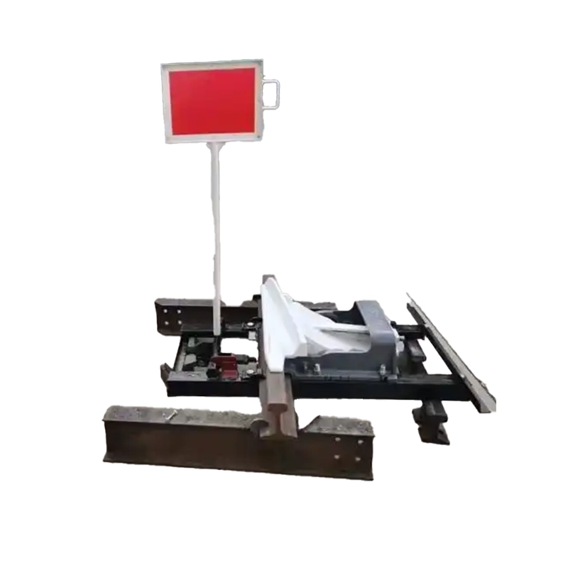
A derailer for mining is a mechanical / electro-mechanical safety device mounted on mine track. Using a movable derail blade/arm or lateral guide, it directs wheelsets to leave their normal running line under commanded conditions, producing a controlled derailment that halts the vehicle at a defined location. The action is repeatable, visibly verifiable, and integrable with local signaling, interlocks and remote control systems.
Key Components & Operating Principle
Derail element (blade/arm): Engineered geometry to reliably deflect wheelsets for intended derailment.
Actuator: Options include manual lever, electric motor, pneumatic or hydraulic cylinder to suit underground power sources.
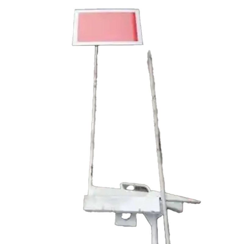
Position & indication: Visual mechanical indicator plus switch/fault feedback.
Mounting & clamp structure: Engineered to sustain impact and enable post-derail clearance.
Operating summary: When in PASS mode the derail element clears the running line; upon a trigger (interlock, remote command or emergency actuation) the actuator places the derail element into WORK position, steering wheels off the rail so the vehicle stops at a designed location while sending status signals to supervisory systems.
Design Considerations & Materials
Validate blade geometry and strength against on-site gauge, rail profile and maximum vehicle mass.
Recommend wear-resistant alloy or heat-treated steel for the blade with anti-corrosion coating; base and clamps in high-strength structural steel.
Design for worst-case runout energy (multiple vehicles, brake failure) to size impact resistance.
Support manual override and remote/interlock control with a fail-safe mode on actuator fault.
Typical Applications
Protection for slope/haulage line termini, maintenance area entrances, personnel work zones, and restricted-area exits.
Works in concert with chocks/barriers as the engineered last line of defense.
Performance & Safety Features
Clear mechanical visual status plus electrical feedback circuits for local and remote verification.
Configurable normal state (NO/NC) and fail-safe strategies to meet site-specific safety policies.
Replaceable wear parts and standardized fasteners to minimize maintenance complexity and downtime.
Interfaces for integration with barriers, alarms and PLC/SCADA to build multilayer protection.
Customization Options
Actuator choice (manual / electric / pneumatic / hydraulic); power ratings and control interfaces tailored to site.
Position feedback options (digital, analog, fieldbus) and redundant signaling.
Grades of wear-resistant and corrosion protection materials.
Installation, Commissioning & Maintenance (Practical Guidance)
- Start with on-site survey to capture rail profile, gauge, mounting conditions, vehicle mass and gradient.
- Conduct factory and site acceptance tests: position verification, empty/load simulation, and interlock logic validation.
- Suggested maintenance: routine inspection of blade wear, fasteners, actuator seals and electrical circuits; maintain service logs and spare parts list.
- Prepare and rehearse derail-clearance and track-recovery procedures to minimize production loss.
FAQs
Q:What types are available?
A: Our Common variants include manual, electric (gear motor), pneumatic and hydraulic actuators — selected based on site power availability and switching frequency.
Q: How is track restored after a derailment?
A:Typical recovery: confirm safety, remove/clear vehicles, inspect/replace damaged parts, realign rails, perform functional checks, and reset the derailer. A predefined emergency-response and responsibility matrix is recommended.
Q: Which is better for underground: manual or electric?
A: If frequent switching or remote operation is required, electric/pneumatic/hydraulic actuation is preferable. For infrequent use and simplicity, manual units are reliable and low-maintenance. Choice depends on operational workflow and power availability.